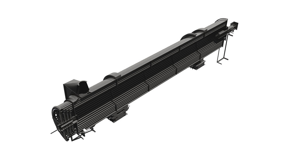
Rotary Kilns
The rotary kilns we design and manufacture are used for thermal treatment of various bulk solids in the cement, building material and chemical industry, waste management, recycling industry, metallurgical industry and rock and associated products industry.
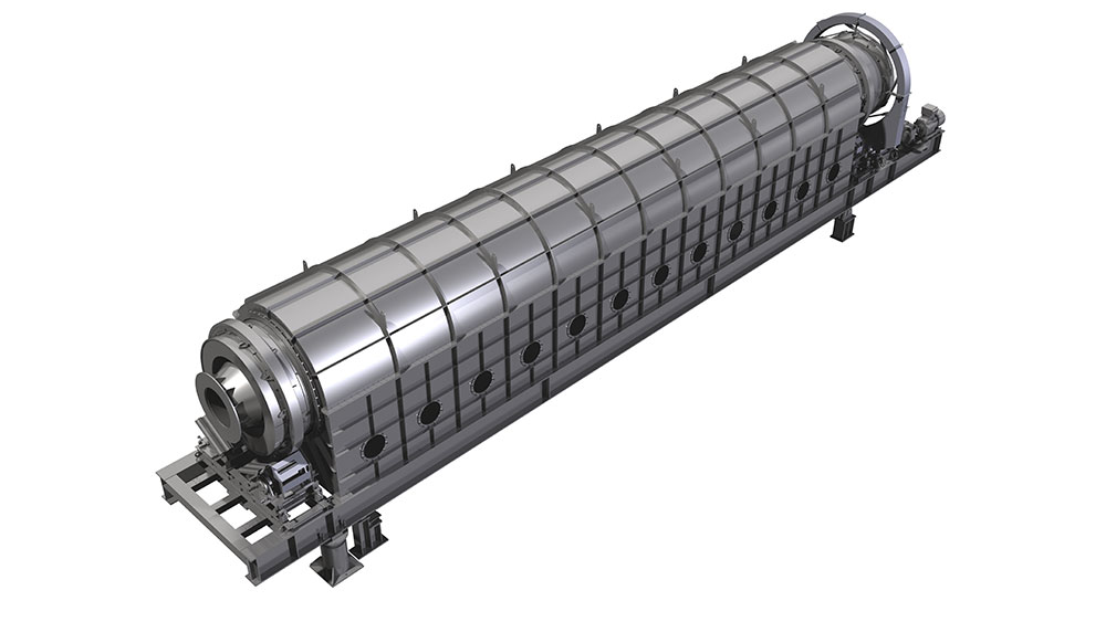
We offer both directly and indirectly heated kilns, with and without inserts.
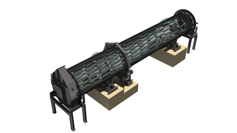
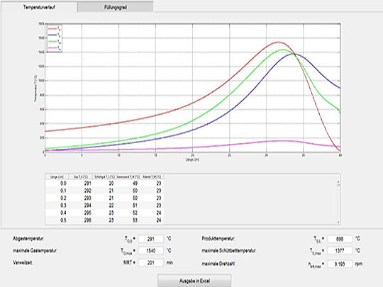
Rotary kilns are used for many different processes involving thermal conversion of free flowing, granular bulk solids. Once inside the rotary kiln, bulk solids can be calcined (lime), sintered (cement), roasted (phosphate), expanded (expanded clay), regenerated (lime slurry), or their crystalline structure can be changed (aluminium oxide). The bulk solid is brought into contact with the hot gas using a counter flow. The thermal energy is supplied by hot gas, that is fed into the kiln at its end. The hot gases can either be produced using a primary energy source (gas, oil or coal), or by using waste fuel, which is more common nowadays due to reasons of energy recovery. The dimensioning of the rotary kiln is determined by the quantification of the procedural possibilities in relation with properties of the bulk solid.
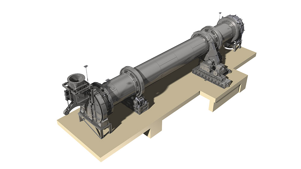
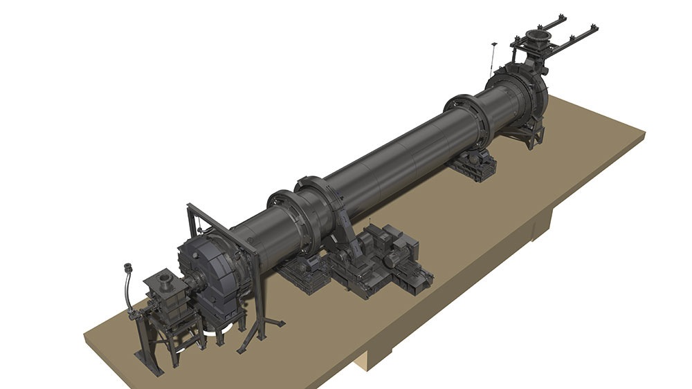
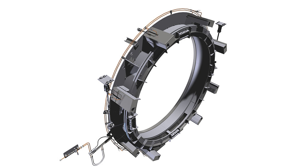
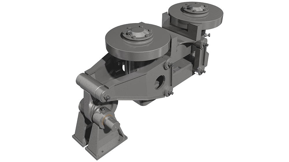
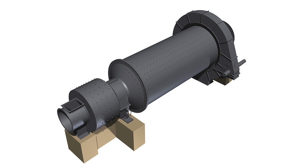
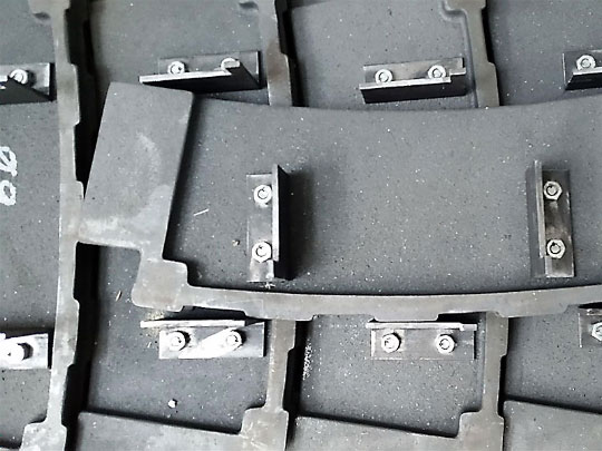
The tyres support the weight of the rotary kiln on the carrying rollers and the stand. Depending on the length of the kiln they are supported at least twice. The tyres can be either welded to the kiln or teethed to it. Another option are loose tyres in the direction of rotation. This can be used to counterbalance the differences of the diameters of the kiln and the tyres due to thermal changes by offering some slip. The carrying rollers can be produced either with a rolling or an anti-friction bearing. Pressure bearings or a hydraulic longitudinal kiln guidance reduce the displacement due to inclination of the kiln and thermal-induced differences in length.
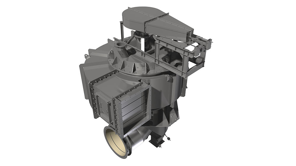
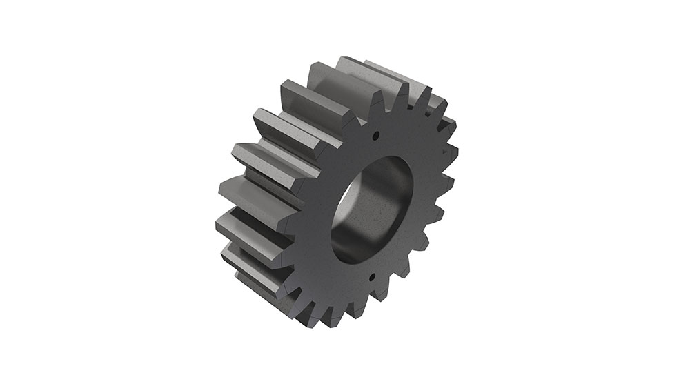
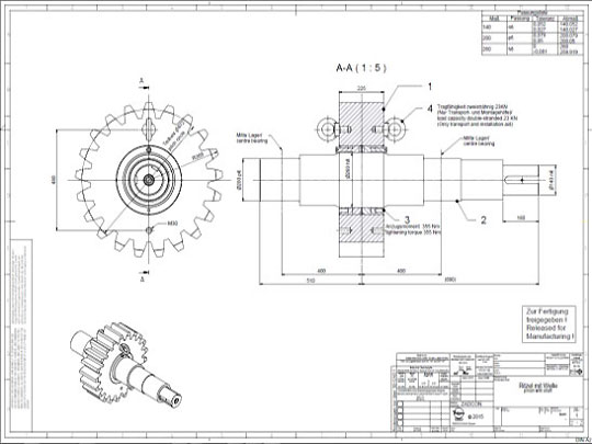
Rotary kilns are driven via chains or girth gear/pinion drives, or via friction drives. To prevent unwanted air entering from the kiln, seals with sliding sealing faces are attached at the kiln inlet and outlet. The sliding sealing faces absorb the longitudinal movement of the kiln. We mostly use pneumatic seals or pull-rope seals. All our rotary kilns are walled. Which fire-proof materials we use is determined by the thermal stress it will be put under, the intensity of wear due to bulk solids and the chemical aggressiveness of the occurring gases. If the material charge is provided as bulk solids dissolved in water, the front part of the kiln will take the function of a dryer. To intensify the thermal process, either cross-shaped inserts or chain screens can be used.
Specific advantages of rotary kilns are:
- equipment that is applicable in many ways to carry out thermal processes alone or in combination with other operations;
- Application for large flowing rates and long required wait times
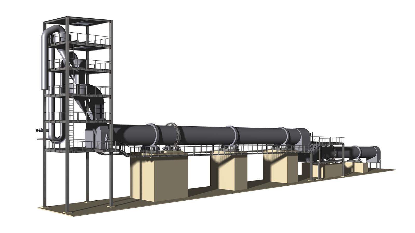
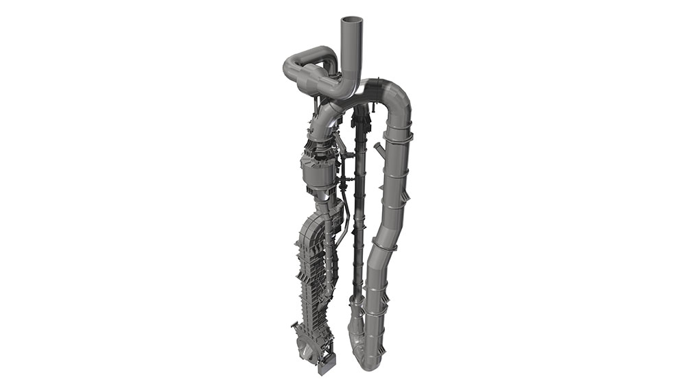
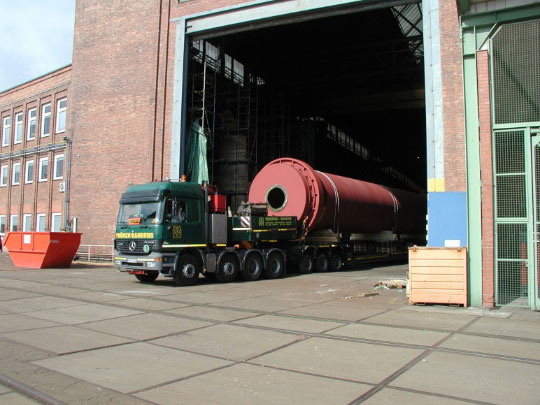
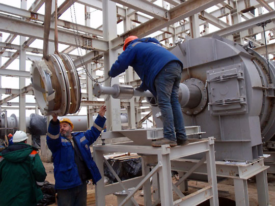
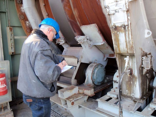
A Rotary Kiln built by ZADCON